Embassy One DIY Guide
Build your own Embassy One with off-the-shelf parts, no permission required
The Embassy One is a powerful open source tool for regaining sovereignty over your
digital life. If you choose to build your own, you can do so for the cost of the hardware
and less than 1 hour of your time. Nobody, including Start9 Labs (developers of
EmbassyOS), can stop you. This is by design.
This guide also available on my substack, but I will be defaulting all my guides to this forum from now on.
Estimated time to complete: 30-60min
30min for hardware build and another 30min to flash/install EmbassyOS. You can save
time by starting the OS flash first (see guide). If you want a convenient plug-n-play
device, or just want to support the cause, you can buy pre-built devices from the Start9
Store. This guide covers the new “official” case from Start9. You can also check out my
previous build guide for another Geekworm case option.
Parts List
• Geekworm NASPi v2.0 ~$60 USD
◦ It is important to get the 2.0 version as it has the ability to power back on
automatically following a power outage.
◦ MAKE SURE YOU GET THE CORRECT POWER SUPPLY FOR YOUR
REGION WITH IT
• Raspberry Pi 4 (8GB RAM model) ~$75-200 USD
◦ These have more than doubled in price in 2022. You may want to shop around,
or buy used if need be.
• Internal SSD (1TB minimum) ~$80 USD and up
◦ 1TB minimum is recommended, however this all depends on your use-case.
◦ 1TB is plenty for a full Bitcoin/Lightning stack OR a good amount of file
storage, but not both if you want your device to be useful for years to come.
2TB or more is recommended if you can stomach the price. Luckily, you can
always upgrade this later, and storage keeps getting cheaper over time.
• SD Card (32GB) ~$10 USD
◦ A larger size is not necessary as it adds no benefit.
• Ethernet Cable (Cat5 or Cat6) ~$2 USD
◦ You may have one laying around. Keep in mind the length you will require, e.g.,
how far away will your Embassy be from your router? 3-6� is normally plenty.
• Speaker ~$5 USD
◦ Not strictly required, but HIGHLY recommended.
• 2-Pin Male-to-Male Power Wire ~$5 USD
◦ Required if using a speaker or Noctua fan.
• (Optional) Noctua NF-A4x10 5v Fan (Get all below) ~$15 USD
◦ Recommended over the less-than-great Geekworm factory fan.
◦ None of the included screws are long enough, so you will need 2 screws
(M3-.50x12), available online or at any hardware store for <$1 USD.
◦ 2x Male-to-Female jumper wires - unfortunately these only come in high
quantities, so you may want to organize a group buy. ~$9
• (Optional) MicroSD to USB adapter
◦ For flashing the OS. Not necessary if you have a way to mount an SD card
already, such as an SD card slot on a laptop.
Estimated total cost:
~$375 with 1TB of storage
~$460 with 2TB of storage
Assembly
Note: If you already have an Embassy and want to upgrade from the existing case to the Naspi,
follow disassembly instructions here.
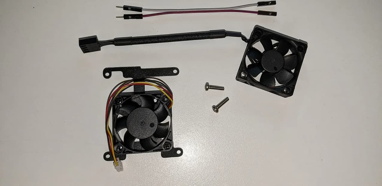
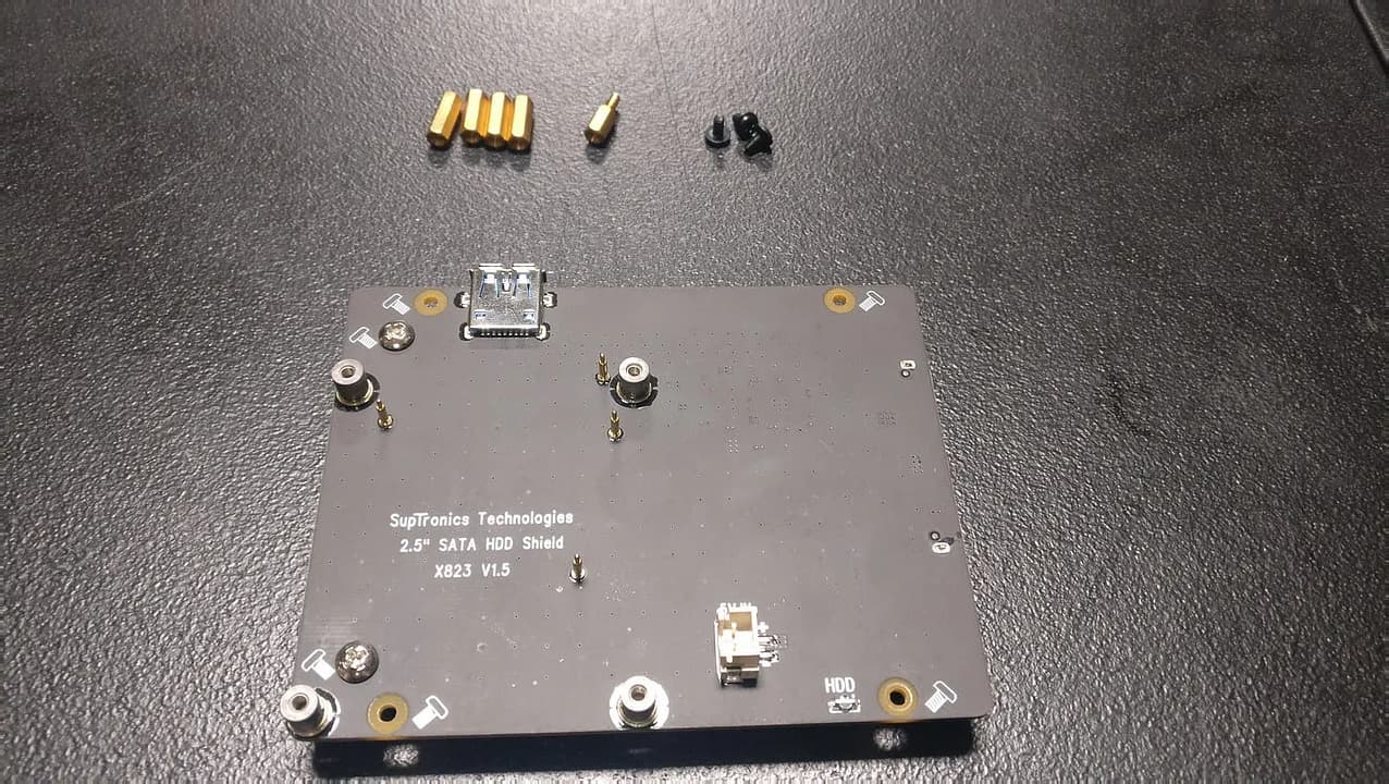
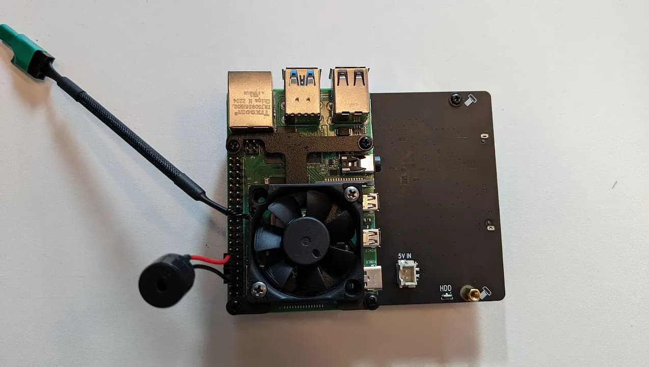
There are several parts included with the case that are not needed for this project. The
picture below shows all the parts that are needed:
A hex tool is included with the Geekworm case for the faceplate along with several of
the parts pictured here. A mini phillips-head screwdriver is the only additional tool
you’ll need for the Naspi assembly.
Step 1: Noctua Fan Prep
If you splurged for the Noctua fan, you will need to secure the jumper wires as an
adapter to the GPIO pins. For this step you need:
• Noctua Fan
• Geekworm Fan on bracket
• Jumper wires
• Aftermarket screws (M3-.50x12)
Note: The Geekworm Fan on the bracket is inside the Naspi case. Use your Phillips screwdriver
to retrieve this part.
Remove the Geekworm Fan from the metal bracket by unscrewing the 2 screws. Keep
the metal bracket nearby, you’ll use it soon. The Geekworm fan can be discarded.
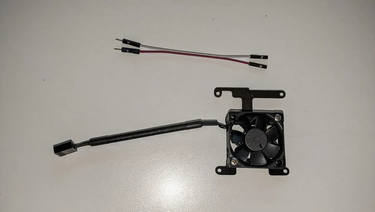
Using the 2 purchased screws, attach the Noctua fan to the bracket with the logo facing
in. The wires should be at the left side of the bracket (as shown) for the tidiest
assembly.
Pick a color for power and ground. In our example, power is purple and ground is
white. On the fan connection there are 2 tabs on one side (shown here at bottom) which
are offset to one direction (shown here to the right).
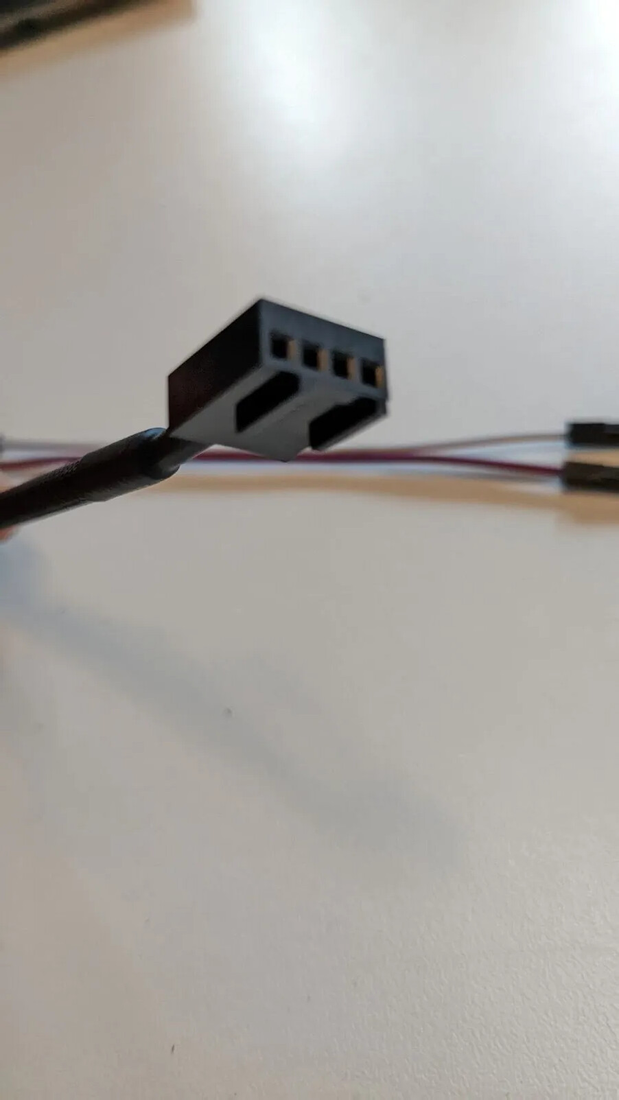
The ground jumper (white in this example) goes into the far right pinhole, with the
power (purple) directly next to it in the second pinhole from right.
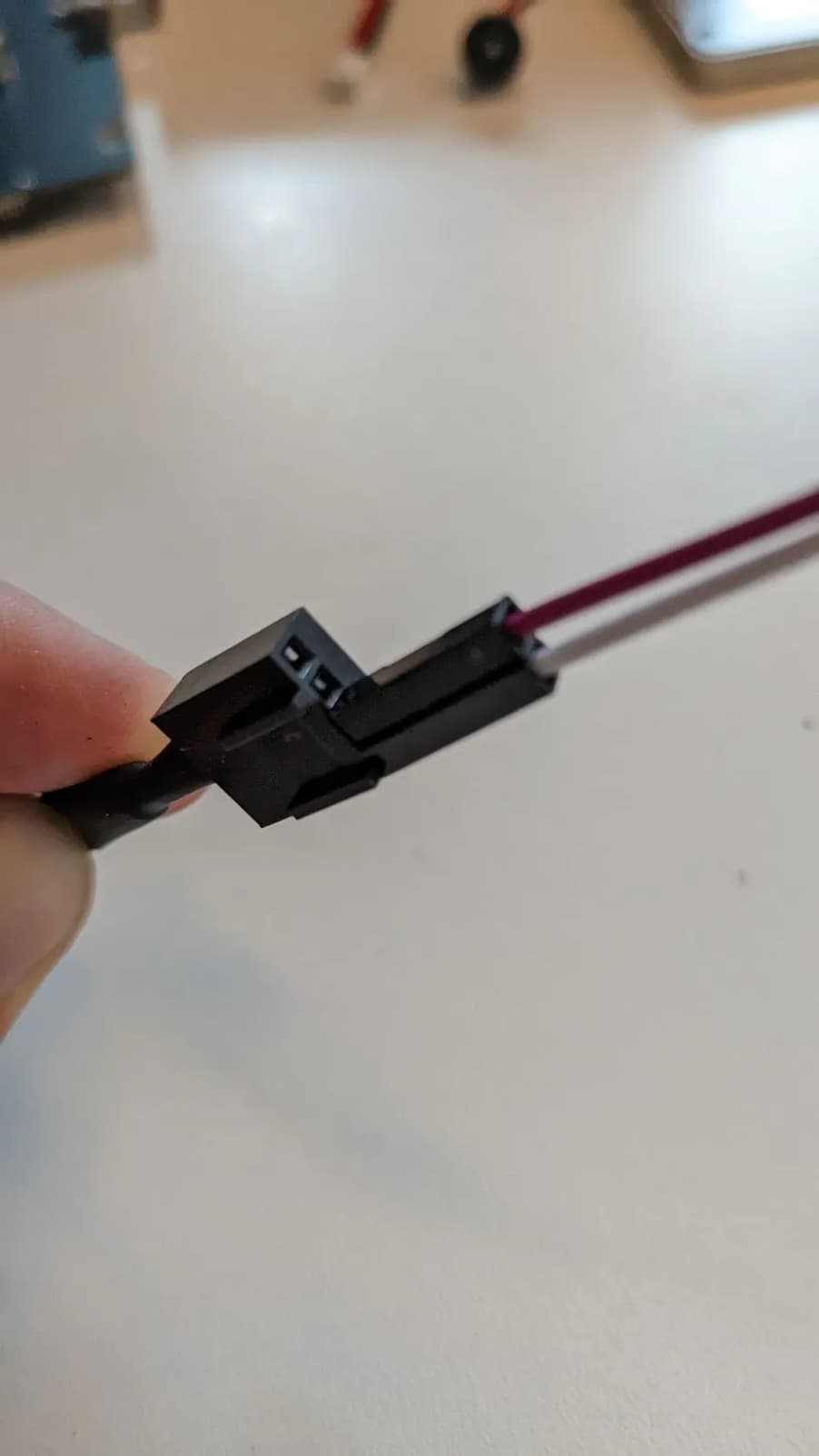
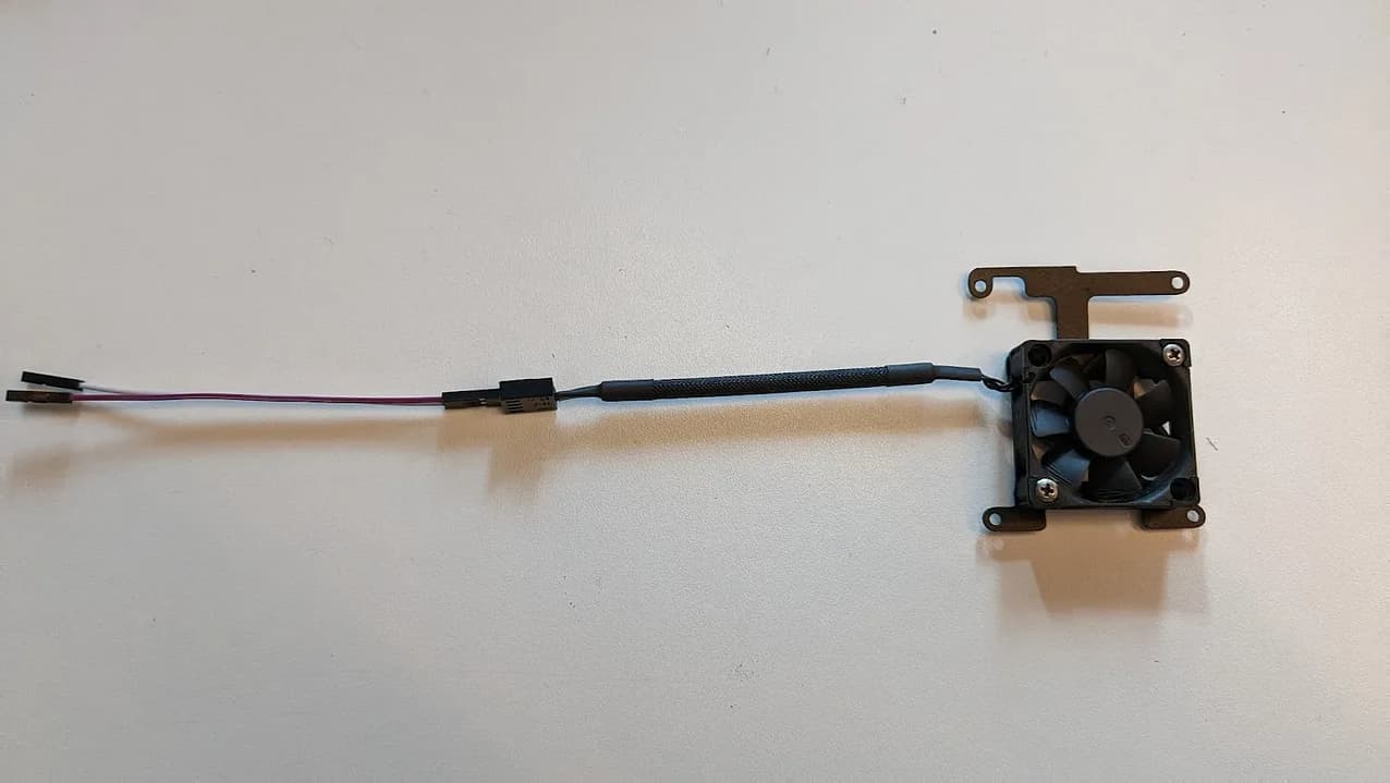
We then want to add a little bit of electrical tape to ensure this connection never comes
loose. The final fan assembly will look something like this:
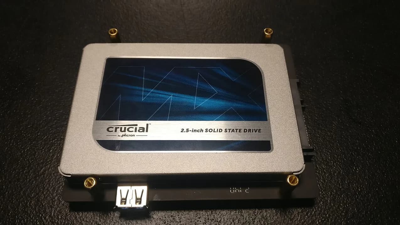
Step 2: Install the SSD to Breakout Board
Components in this step:
• SSD
• SSD Breakout Board
• 2 silver screws
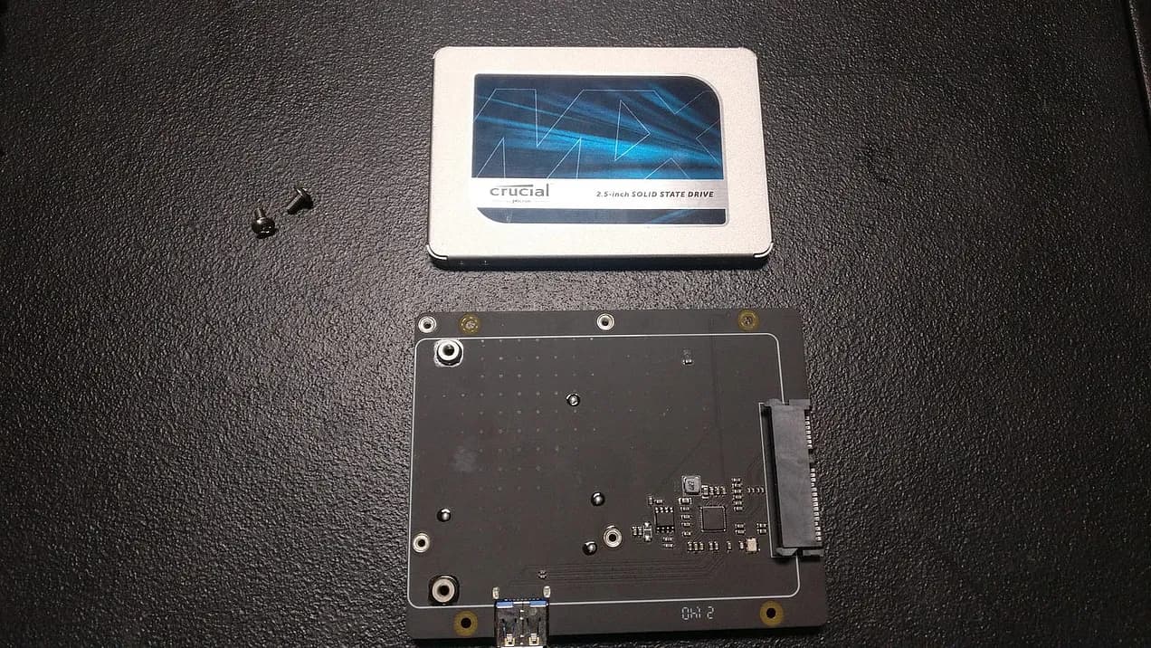
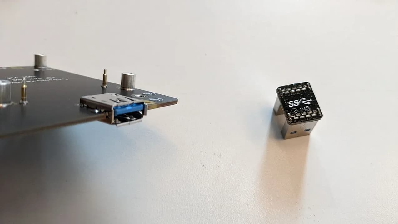
Remove USB 3.0 Connector from the USB port and set it aside.
Insert the SSD into the gray SATA port connection seen on the board. Use the 2 silver
screws to secure the drive to the board from the underside. There should not be a gap
between the SSD and the board stand-offs. If there is a gap, unscrew and retry the
screws holding the SSD to the board so that the screw thread catches quickly.

Step 3: Prep SSD Board for Assembly
Components needed:
• 4 female-to-female brass spacers
• 1 female-to-male brass spacer (the longest one)
• Board with SSD
• 3 black screws (button-head)
Note: There are 6 female-to-male spacers included in this build, 1 (the longest) is used in this
step and 4 (uniformly sized) are used in a future step. There is 1 female-to-male spacer that is
slightly smaller than the other 5; this smaller spacer can be discarded (see video).
Through the hole in the bottom right corner (the corner that says “HDD”) connect the
small male-to-female spacer (non drive side) to a female-to-female spacer (drive side).
The remaining 3 female-to-female brass spacers go on each of the remaining 3 corners
(drive side), using the 3 black screws.
These spacers will be used to secure the internal assembly to the case.
Step 4: Prep Raspberry Pi
Install the speaker on the Pi, starting on the 3rd pin on the outside row from the end
where the SD card slot is. The word ‘speaker’ on the connection will face away from the
board.

Scroll down to the bottom of Step 6 for a detailed pinout diagram if you are not certain.
Step 5: Install Raspberry Pi
Components Needed:
• Raspberry Pi with Speaker installed
• SSD Breakout Board with SSD and Brass Spacers installed
• 4 Male to Female Brass Spacers (uniformly sized)
Note: There are 6 female-to-male spacers included in this build, 1 is used in a previous step and
4 are used in this step. There is 1 female-to-male spacer that is slightly smaller than the other 5;
this smaller spacer can be discarded.

Place the Raspberry Pi on top of the SSD board such that the USBs from each board
are stacked. Secure Raspberry Pi to the Board using the 4 male to female spacers
through the holes in the Raspberry Pi board into SSD Board as indicated.
The 4 male-to-female spacers can be finger tight at this stage, most importantly be
sure they are threaded correctly. They will be tightened in the next step.
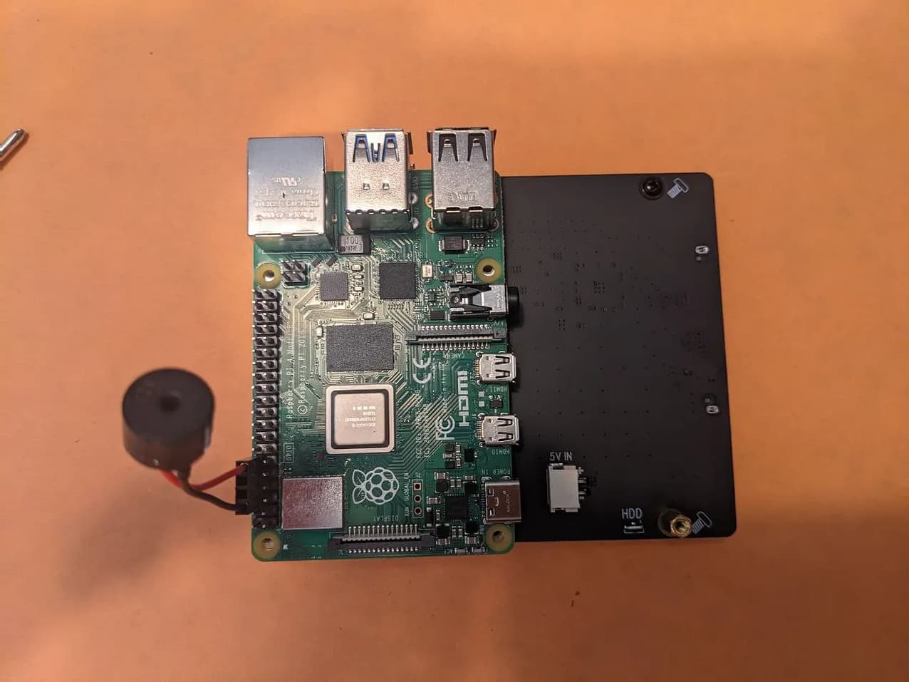
Secure using 4 male-to-female spacers. The fan bracket will sit on top of these.
Step 6: Install Fan
Components Needed:
• Raspberry Pi Assembly
• Fan with Fan Bracket (Noctua or Geekworm)
• 4 black screws (button-head)
Tuck the speaker out of the way as shown. Mount your chosen fan such that the fan is
over top of the big silver chip - this is the CPU. Position of the bracket shown below is
without a fan attached, for clarity purposes.
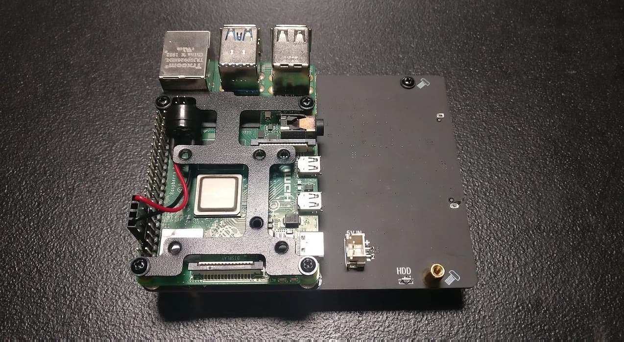
Using the 4 black screws, mount the bracket to the board by screwing them into the 4
male-to-female brass spacers and tighten.
Now, let’s plug in the fan wires. The ground (black wire) goes directly next to the
speaker connection (on the left if looking from the outside). It can go to any other
ground if desired. For power (red wire), you have an option. For better cooling
performance, but some additional fan whine (noise), use the first outside pin (5v - #2 in
the image below). For quieter operation, but slightly degraded cooling performance, use
the first inside pin (3v - #1 in the image). Start9’s default build is 3v (quieter operation),
but you can choose either, and can change at any time by switching this pin. The black
box in the image below indicates the location of the speaker.

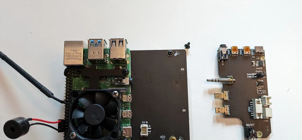
Step 7: Install Power Management Board
Components Needed:
• Raspberry Pi Assembly
• Power Management Board
• 2 cable power wire
• 1 black screw (button-head)
Carefully, Slide the 2 micro-USB and 1 speaker connector laterally into the Pi. This
requires some wiggling and does require careful force to maneuver into place (see
video). You will know it is in all the way when the screw hole is over the female spacer.
Secure with black screw at the bottom of the board, near the power button.

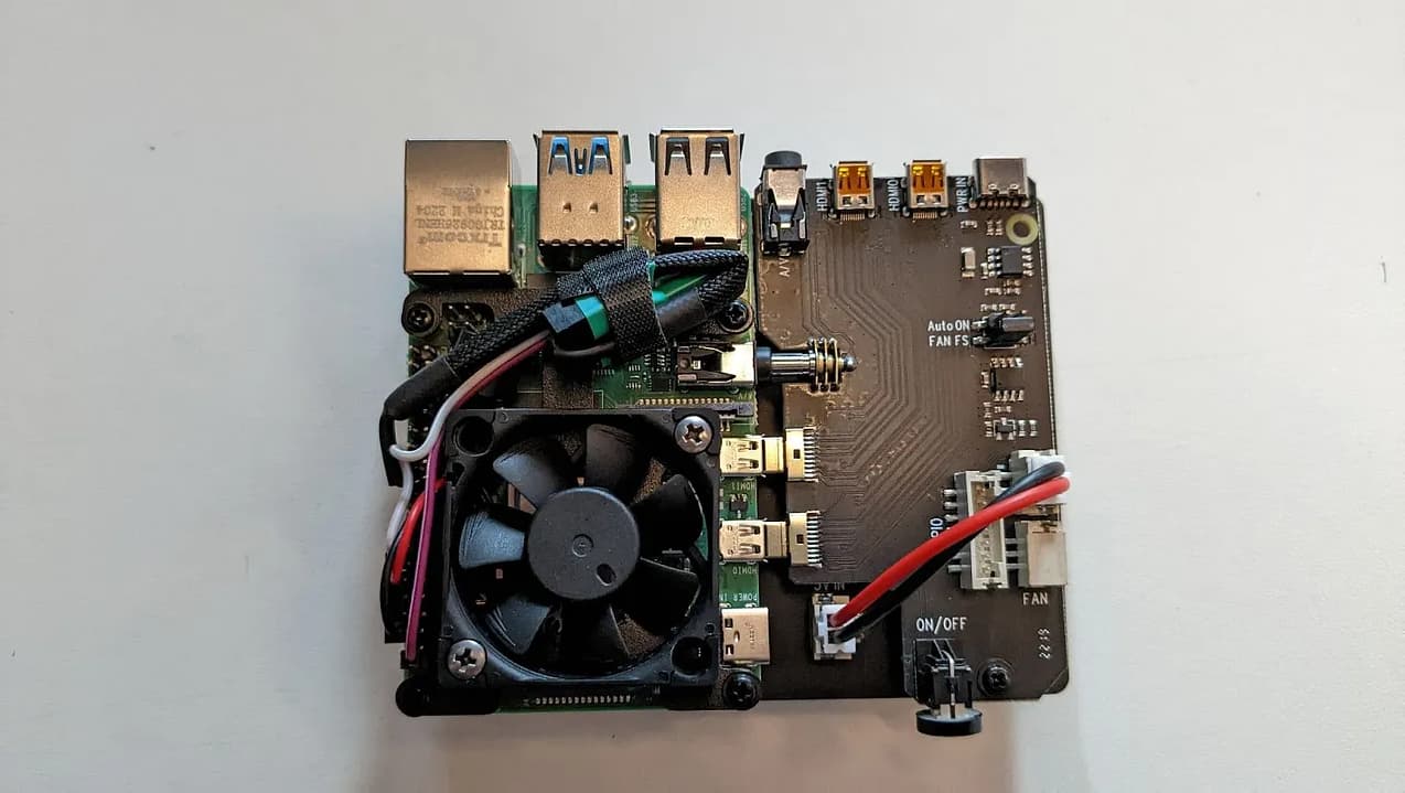
Remove cover to the connection to the left of the power button. Install the 2-pin power
cable from the SSD board to the power board. Route the fan wires around the fan such
that they do NOT cross over the top of the fan. Use a piece of velcro or electrical tape to
secure. See below for our recommended wire management set up.
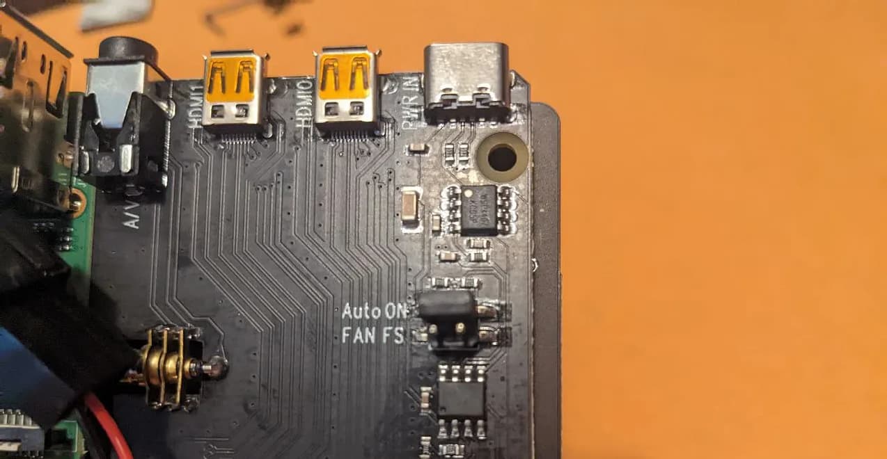
Step 8: Setup “Auto-On”
Setup auto on by moving black jumper up to “Auto-ON” as shown. This is vital as it
will allow your Embassy to power back up following a power failure.
Step 9: Install to Case and Finalize
Components Needed
• Fully Assembled Board
• Naspi Case
• Acrylic faceplate (recommended for WiFi)
• 4 black screws (flat head)
The case comes with an option of a metal or acrylic front faceplate. If you intend to use
a Wi-Fi connection on your Embassy One, you should opt for the acrylic faceplate. Peel
the protective film off BOTH sides of the acrylic faceplate. Swap out the metal faceplate
for the acrylic faceplate. Remove the metal faceplate by unscrewing the hex screws with
the included hex wrench. Secure the acrylic faceplate using the same hex screws.

Next, install the assembly to the case. Be careful when tucking in the wires, and ensure
they will not interfere with the fan, or your device will get hot and performance will be
degraded. The cable should route around the fan and not on the top of it.
This step can be delicate, and is crucial to ensuring longevity for your device (see video).
This is a powerful piece of Freedom technology. Respect it and TAKE YOUR TIME!!
Secure the back plate to the case with 2 screws, lining up the openings with the ports.
Secure the board assembly to the case with 4 flat head screws in the bottom of the case.
If you notice that they have nothing to thread into, then you likely inserted the
apparatus upside-down.
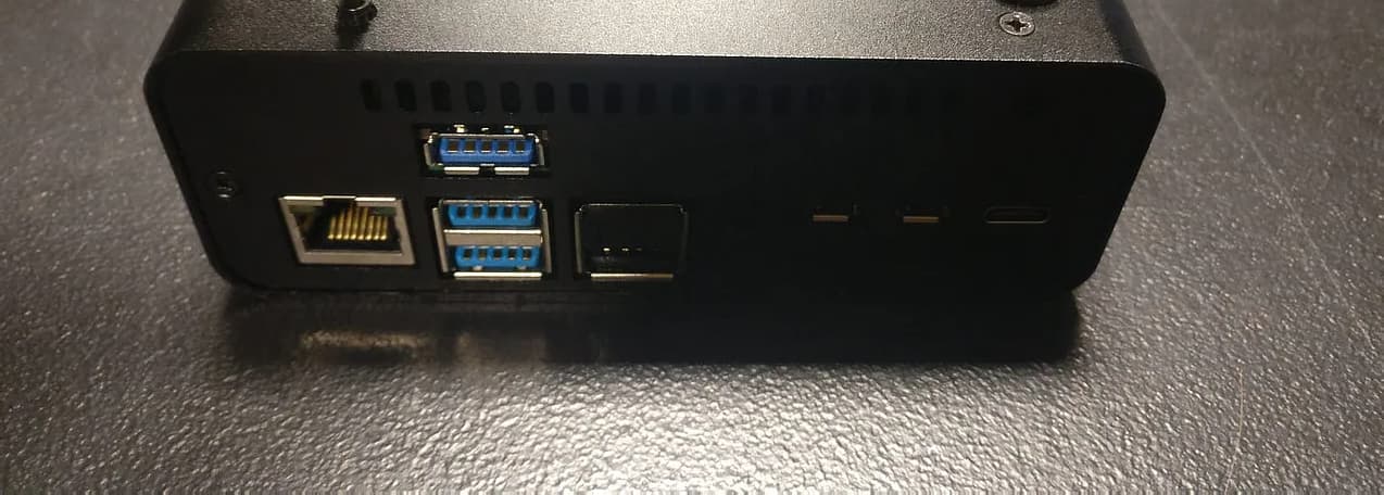
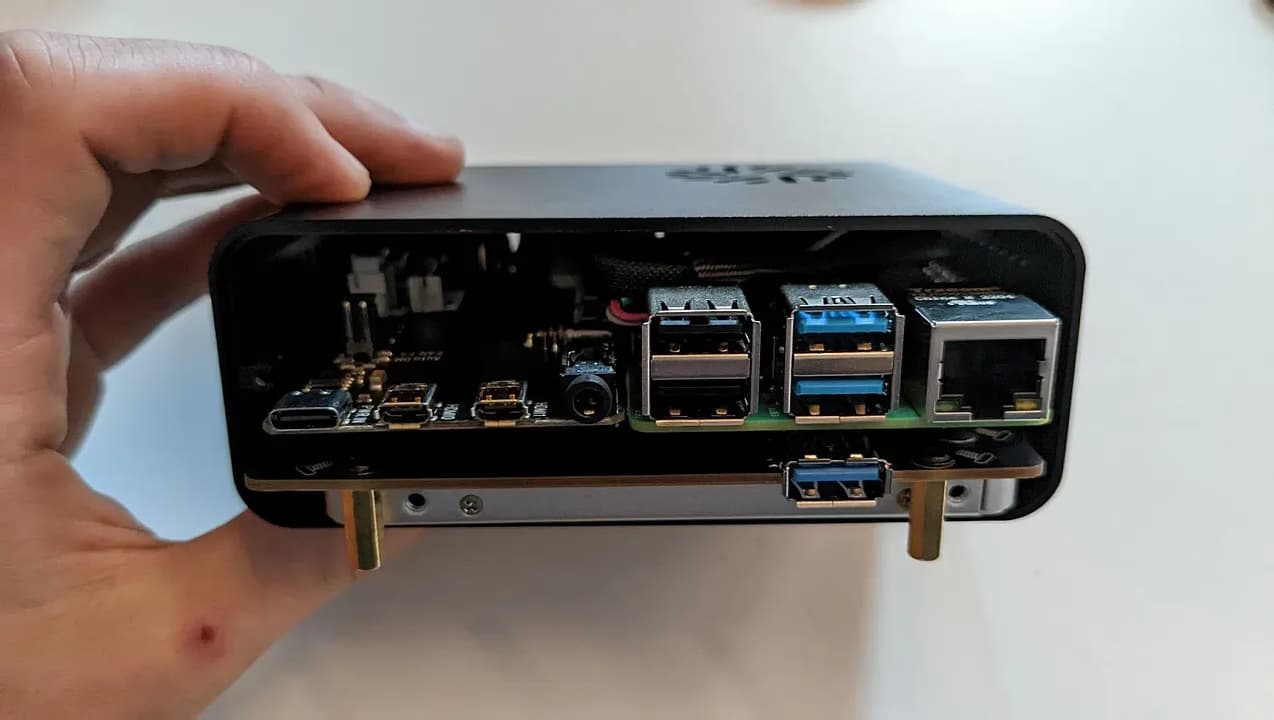
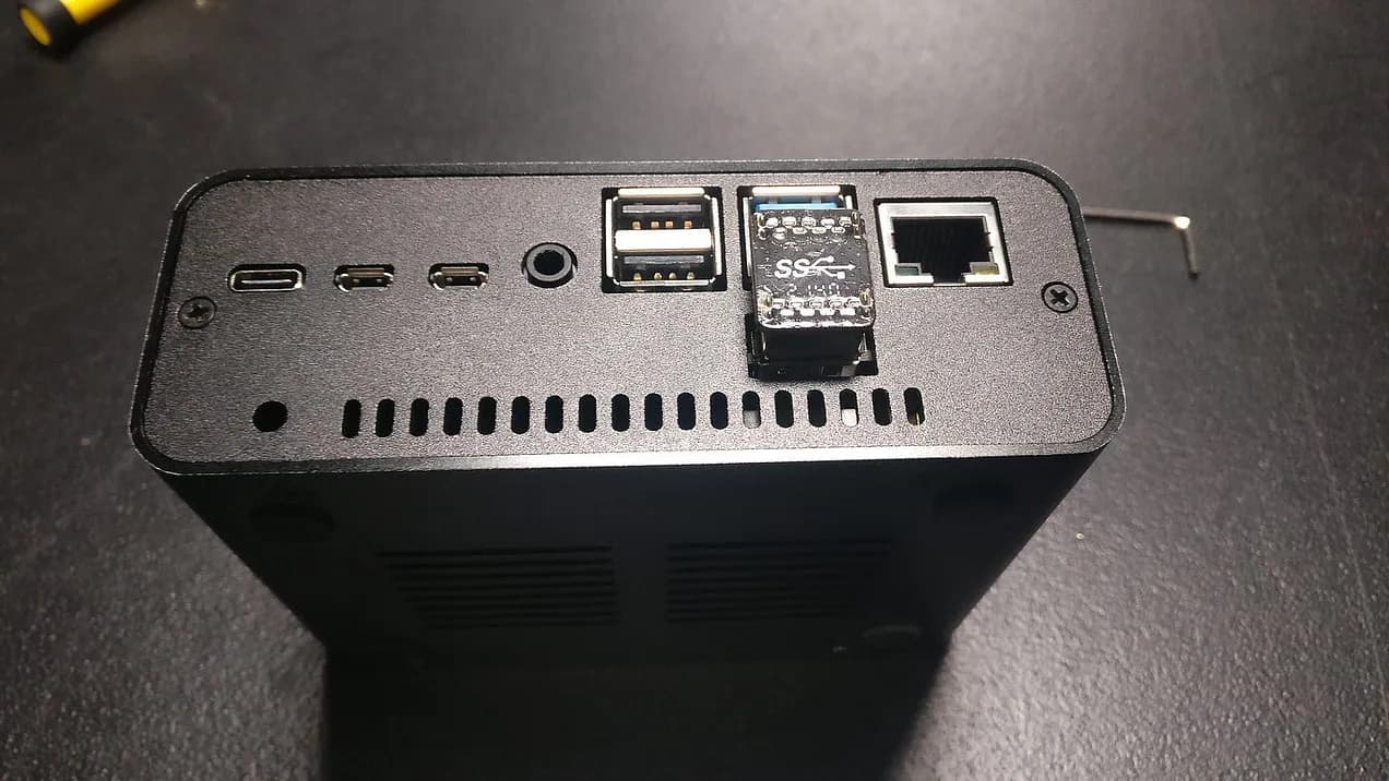
Plug in the USB loop on the back as shown. This is the data connection between the
SSD and the Pi computer.
Finally, add the protective rubber feet to the bottom. You’ll have several parts leftover
that can be discarded.

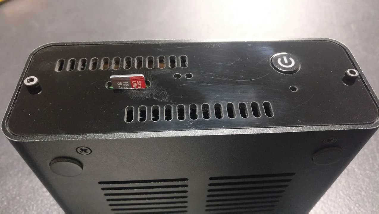
If you haven’t done so already, install EmbassyOS by following the Start9 Guide. Insert
the SD card when you are done.
Then plug in your ethernet to your router and the power to an outlet and listen for the
bep and chime sounds.
You’re done! Congratulations! You can now host your own private cloud, with no third-
party permission required!!
Protip: Blow the dust out of your device 1-2x per year to maintain peak performance.
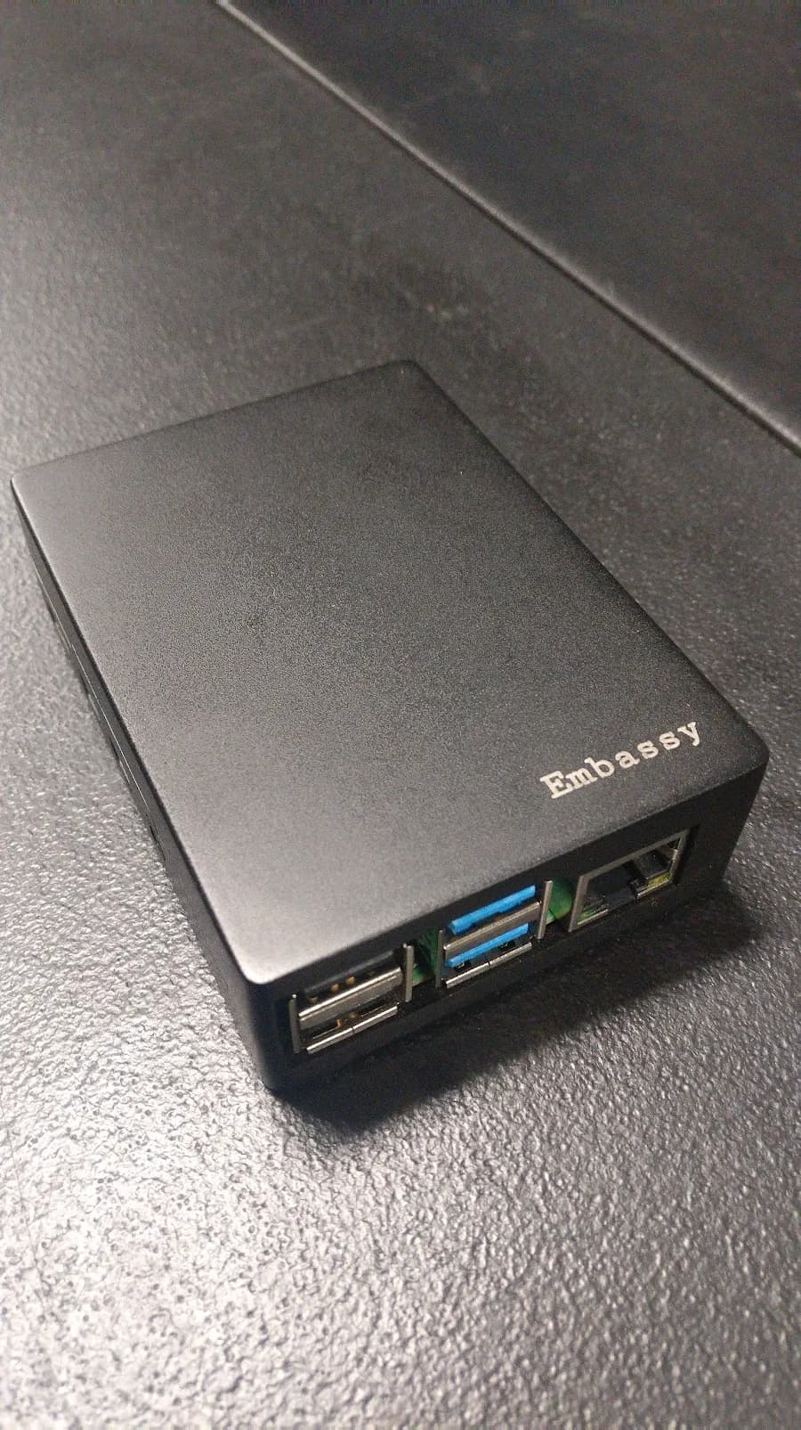
Appendix: Transfer Embassy from Existing Case
If you already have an Embassy and want to upgrade to the Geekworm NASPi v2.0 case,
you’ll first need to take apart your Embassy.
Upgrading from the old case to the new Geekworm NASPi v2.0 case is relatively
straightforward. The only “gotcha” is that if you have an external drive, such as a
Samsung T7, you will need to do a backup, get an internal drive, and restore to that new
internal drive after moving to the new case.
To begin, remove the 4 screws from the bottom of the case and split the case open. You
can leave the SD card and speaker installed if you wish; they will not be moved.

Remove the Pi from the case and peel off the 3 blue pads from the chips. The new case
utilizes a fan, rather than being a heatsink-style like this case, so they are not needed.
You may wish to keep them with the old case for another RasPi project.
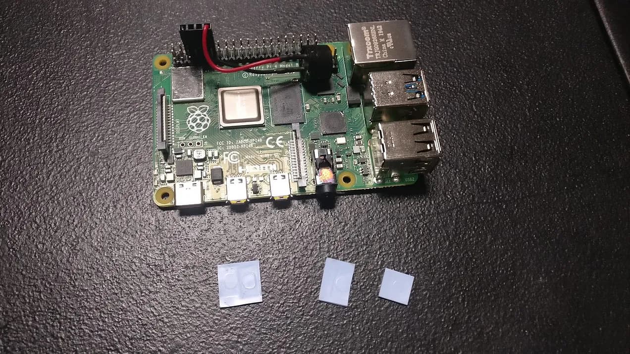
Set aside the RasPi for later assembly, and locate your SSD/enclosure.
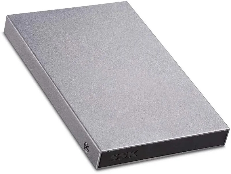
Unscrew the 2 screws on the outside of the enclosure. Slide the SSD out of the
enclosure and remove the 2 additional screws. Unplug the SSD by sliding it at an angle
out of the plastic frame.
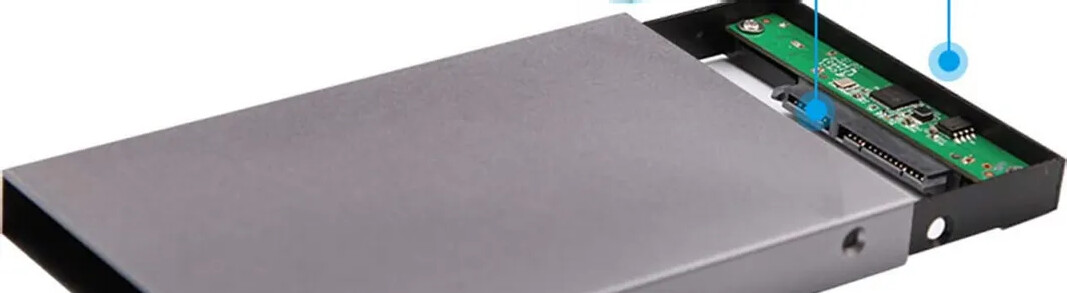
That’s it! You are now ready to continue to the Assembly portion of the project.